|
Tire recycling line
2500 kg/hr
Model
TRM102 |
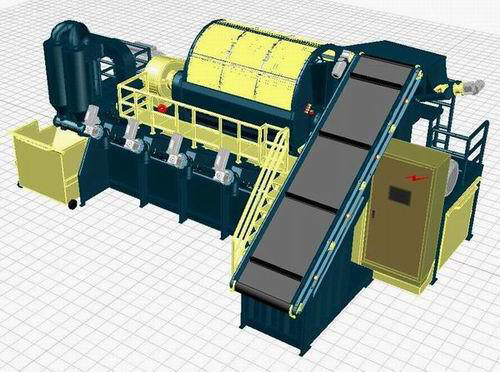
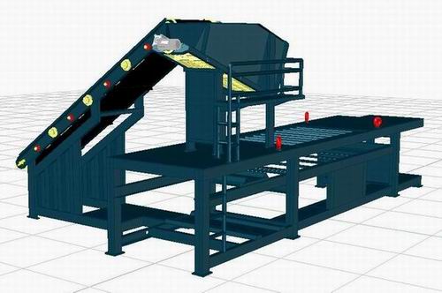
Tire recycling line 2500 kg/hr
Tire
recycling line TRM102 is the modification to existing lines to give the
user maximum production capacity about 2500 kg/hr with minimum power
consumption about 222 K.W. in addition to many advantages like it is
compact in design, requires less than 200 square meter to install it,
only three workers can operate the line with full capacity, only four
workers can install the line in one day. Besides
many other advantages which are hard to be found anywhere.
These
modifications are a result of many years in tire recycling field. After
manufacturing tire recycling lines and recording the required
modifications, we made this new line to be a new step in tire recycling
field.
|
Advantages of tire recycling line |
The most
advantage of tire recycling line is that capital return is very fast
where you can return your money within one year in average. In addition
it has flexibility to produce many powder sizes to meet market
requirements.
The
production line has advantages in its design where it is compact in size
which means less power consumption, less powder transportation in
production line, Easy in shipping and installation.
The line
is provided with programmable feeding system which could be programmed
through control system to required feeding rate. The line is provided
with cables and maintenance tracks which are assembled during
manufacturing and will not be disassembled during transportation.
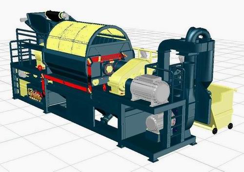
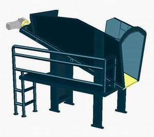
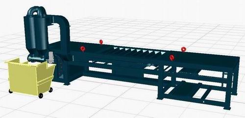
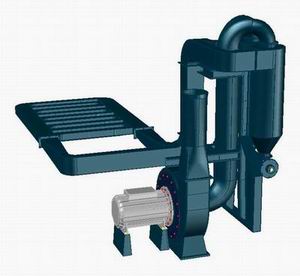
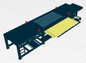
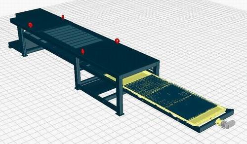
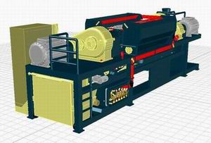
Rear view of production line
The
unique shredding system can shred the whole tire into powder in one path
with rate 2500 kg/hr using two electric motors each of 90 K.W. and using
trommel system to pass the powder less than 3 mm to the line where it
returns the rubber more than 3 mm to shredding system again.
The
trommel passes the steel wires just after it is separated from the tire
and it will return it back to cutting system which gives long life
cutting blades and allow us to use only one magnetic separator for all
the line.
Generally
we were using magnetic separator after shredder to protect the grinder
and use magnetic separator after grinder to separate fine steel; Now we
compact shredding and grinding systems together and we don`t need more
than one magnetic separator.
The line
is provided also with screening and packing system to pack the four
output powder sizes in adjustable packs which could be programmed
through control system.
The
packing system still works till it reach the programmed weight of the
pack; then the packing process stops and the powder is collected in
internal container till you change the pack and push the packing button
again.
Fiber
separation system is provided with air lock which is operated by
electric motor and this lock allows us to discharge the fiber to
external containers without stopping the production line. During fiber
containers changing; air lock stops charging out the fiber and keeps it
inside cyclones till you change the container and bush the air lock
button again to operate it.
Magnetic
separator is provided with internal pocket which is opened automatically
to collect the steel wires till you change the steel container and it is
closed automatically when you insert steel container in its location.
The
production line is assembled on a frame with unique design which allow
us to draw any system of the line quickly and easily without dismounting
any other units.
All line
units and systems are assembled in drawer shape in the frame to ease
shipping, installation and maintenance.
|
General technical specifications: |
-
Production line is manufactured with main European components
-
Production line is 7.5 m length , 4 m width and 3.5 m height
-
Installation required area is 200 m^2 in addition to storage and
utilities areas
-
Required workers are 3 per shift
-
Production line capacity is 2500 kg/hr of input tires
-
Adjustable feeding system to be adjusted according to tire sizes
-
Shredding and grinding system to shred full tires to less than 3 mm in
one path
-
Fiber separation system to separate fiber in external containers
-
Magnetic separation system to separate steel in external containers
-
Screening and packing systems to classify and pack the powder in 4 sizes
-
Cooling system is provided
-
Average water consumption is 100 lit/hr
-
Average power consumption is 222 K.W.
-
Whole production line weight is about 25 ton
-
Central control panel using touch screen to operate and simulate the
line
-
After sales services and spare parts are available
-
One year warrantee
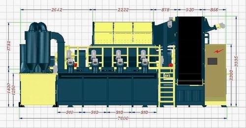
Main dimensions of production line
|
Systems of production line |
-
Feeding system: It
consists of belt conveyor to arrange feeding rate and vibrating table to
direct the tires to shredding system.
-
Shredding and grinding
system: it consists of 68 cutting blades with 20 different designs to
shred, grind and pulverize the rubber into 3 mm powder in one path.
-
Trommel system: It
passes the powder less than 3 mm to production line and return the
powder more than 3 mm to shredding system again.
-
Fiber
separation system: it consists of fiber suction unit to draw the fiber
from the powder and filtration system to filter the air and separate the
fiber from it.
-
Magnetic separation system: it is permanent magnetic drum works on
electric motor and rubber belt to separate the steel wires to steel
container.
-
Screening system: It is a set of changeable screens with different mesh
sizes to classify the rubber powder into four different sizes.
-
Packing system: It is a set of augers for each mesh size and each auger
has its own container to collect the powder in it temporally.
-
Cooling system: It cools the cutting blades in different zones with
different water pressure and different flow rate. The system controls
filling of water tank.
-
Electric
control system: It is the control panel with touch screen to simulate
and operate the line. Also the control system includes fixed cables and
cable tracks.
-
Maintenance tracks: It is a set of stairs, ladders and tracks around
production line to ease maintenance and follow up operations.
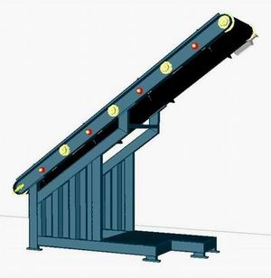
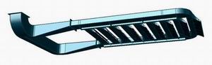
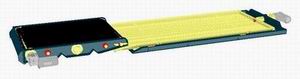
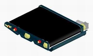
Feeding system starts in belt conveyor of 90 cm width and 4 m
length, it is loaded on robust base and operated via electric motor 3 hp
and reduction gear box 1/100 and variable speed electric system.
Belt linear speed could be controlled from 7 m/min to 14 m/min
and which means 2 to 3 ton/hr of tires where tire size not more than 90
cm and average weight about 8 kg.
Tire feeding system
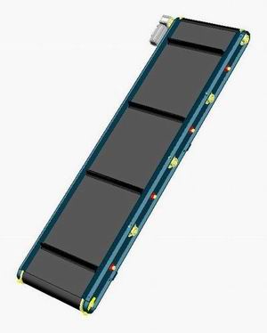
Conveyor belt is provided with horizontal fins each 90 cm of belt
length. These fins with 70 mm high and acts as a gauge to adjust feeding
operation where operator have to put one tire at each fin.
Belt
conveyor of feeding system
The belt high at lower end is about 80 cm which is suitable for manual
loading of tires and belt inclination is 35 degree to the ground which
allows high friction force to permit the tire chips from sliding in case
we feed the line with rubber chips.
Belt conveyor unit
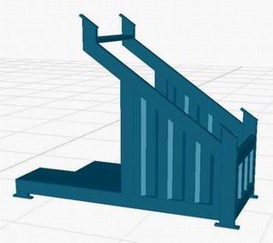
Belt
conveyor base
After feeding the tire to the line; It is directed to shredding system
by a vibrating table which rotate the tire and feed it to shredding
system in vertical position to ease shredding process. Vibrating table
is mounted on elevated frame with inclination of 20 degree to the ground
which is suitable for feeding process and allow easy access to lower
parts of production line.
Vibrating table of feeding system
Vibrator
Vibrating table is vibrated using specially designed vibrator which is
driven through 2 hp electric motor and reduction gear box 1:3 reduction
ratio. The linear velocity of vibrating table is 3.5 m/min. Vibrating
table is provided with upper hopper which could be used to feed the
production line with rubber chips and it is provided also with side path
which is used in follow up and maintenance operations.
|
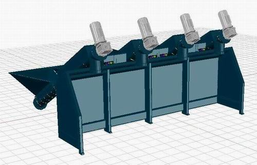
2- Shredding and grinding system |
Shredding and grinding system accepts the tires coming from feeding
system and shred it to rubber powder less than 3 mm in one path. The
cutting blades have special designs which are settled after sires of
trials on traditional shredders. And it could be considered as a new
step in shredding systems.
The shredding system has 68 cutting blades with 20 different designs and
is assembled on two rotating axes with 2200 mm length. Each axe is
driven from separate electric motor 90 K.W. and reduction gear boxes to
finally rotate the axes with 30 rpm and this system can shred 2500 kg/hr
of recycled tires.
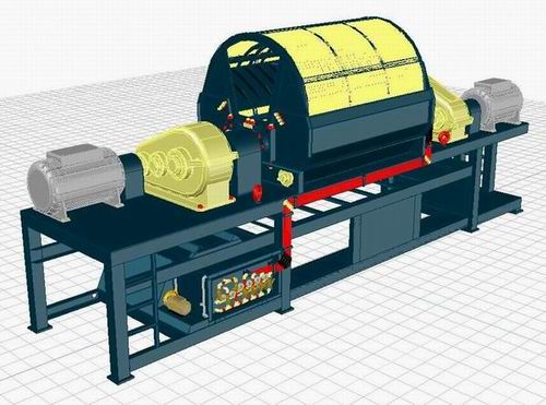
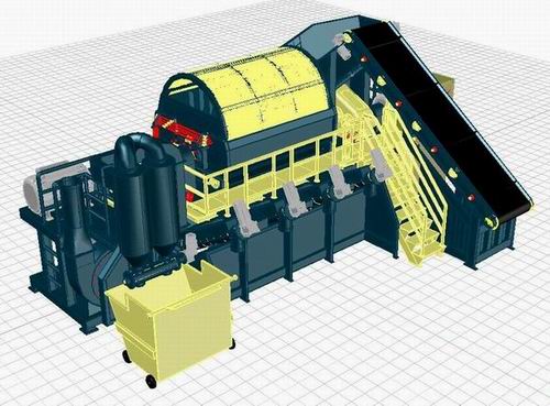
Shredding and grinding system
This new design of shredding system acts as four machines in one where
we were using primary shredder to shred the tires to 50 by 50 mm chips
and secondary shredder to shred these chips to 16 by 16 mm and grinder
to grind these chips to 5 mm and final grinder to grind these chips to a
powder.
Now we do these processes in one unit of production line which means
more production capacity, less power consumption and compact design.
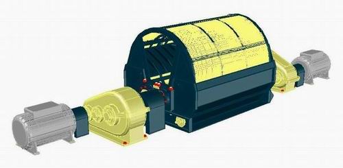
Shredder, Grinder and Trommel units
During cutters maintenance, the upper trommel half is dismounted and so
the internal hopper of shredder, then the desired axe could be removed
with all its cutters and it is easy to change or re-sharpen the blades,
then reinstall the axe, internal hopper and trommel half in its location
and operate the line without disconnecting the cooling connections
during maintenance
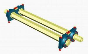
Axes of shredding and grinding system
Parallel to shredding system there is cooling system which sprays cold
water on cutting blades with different pressures and flow rates
according to blades designs. This system allows the blades to be just
cooled without wetting the rubber or needing drain line.
Parallel to shredding system; There is trommel system which passes the
rubber powder less than 3 mm to production line and return the rubber
chips more than 3 mm to shredding system again.
Trommel unit is made in two halves to ease mounting and dismounting,
rotating unit is assembled from robust rotating frame and a set of
identical screens which are fixed on rotating unit. Rotating unit is
driven via 2 hp electric motor and reduction gear box 1:8 reduction
ratio which leads to rotation speed of the trommel 10 rpm.
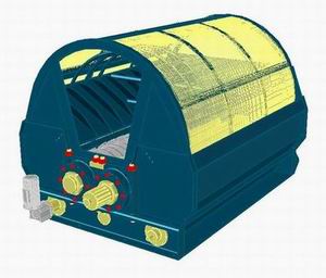
Trommel with shredding system
Trommel unit
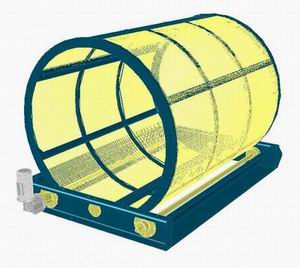
The trommel is closed carefully from sides to prevent the rubber to leak
from sides and the rubber powder is allowed only to pass through the
trommel mesh which is 3 mm in size and so we guarantee that the powder
is less than 3 mm.
In addition; the trommel passes the steel wires just after it is
separated from the tire and prevent it to return to the cutters again
which increase blades life and allow us to use single magnetic
separator.
The trommel system is provided also with outer cover which is easily
removed during maintenance and screens changing, The trommel system is
provided with internal hopper which directs the returned rubber to
cutting area, The rotating unit has a horizontal fins which acts as
frame supports and acts as elevating fins to elevate the rubber.
|
4- Fiber separation system |
After rubber shredding to less than 3 mm; it is moved to other system of
production line which is fiber separation system in which the fiber and
nylon are separated from rubber powder.
Fiber separation system in the line
Fiber separation system starts in suction unit where the fiber are drawn
from the powder when the powder passes through suction gaps and before
it reaches to the next floor.
Fiber separation system
Special suction angles of suction unit helps the suction unit to draw
only the fiber and nylon from powder where it leaves the rubber powder
to pass to next system. In addition; suction unit draws also dust
resulting from shredding process and so the rubber will be free from any
existing dust. The suction sensitivity is adjusted from general control
of the production line.
Suction unit with its suction angles
After the fibers are sucked; the air passes with these fibers through
air ducts till it reaches the air filtration unit and it is within fiber
separation system.
Air filtration unit passes the air with fiber to two cyclones where the
fibers fall inside the cyclones and the clean air pass to the next unit
which is blower unit and hence to the atmosphere.
In addition to cyclones; secondary filer is mounted at blower exit to
ensure cleaning of exhausted air.
The blower works on electric motor 20 hp, 2800 rpm and it is controlled
from general control of the line and hence the blower pressure is
controlled to just draw the fiber and leave rubber powder.
Cyclones and air lock
To get the fiber from the system in continuous operation; we use air
lock at cyclones exit where the air lock rotates to bring the fiber from
inside the cyclones to outside it and drop it in outer fiber containers.
When the fiber container if full; the air lock stops automatically and
you will hear and see warning to change the container, after a certain
time; the air lock works automatically even there is not fiber container
under the cyclones and so it prevents blocking of fiber inside the
cyclones.
You can operate or stop the air lock manually by push buttons beside air
lock for emergency. The air lock is operated by electric motor 2 hp and
reduction gear box 1:8.
|
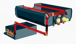
5- Magnetic separation system |
After fiber separation from the rubber; the rubber is collected by
vibrating table 125 cm width and 250 cm length, it is same area of fiber
suction unit. This vibrating table is mounted to production line frame
as side drawer to ease mounting and installation.
Collection vibrating table
Vibrating
table is operating from vibrator unit which is driven from electric
motor 2 hp and reduction gear box 1:3. At the end of vibrating table we
mount magnetic separator which extract the steel wires from moving
powder.
Magnetic separator with collecting table
Magnetic
separator works on permanent magnet to extract steel wires and belt
conveyor to move these wires to steel container.
The
magnetic separator is provided with small pocket to collect the steel
wires in it till you change the steel container and the pocket opens and
closes automatically with container insertion. When the container is
full; you will hear and see warning to empty steel container.
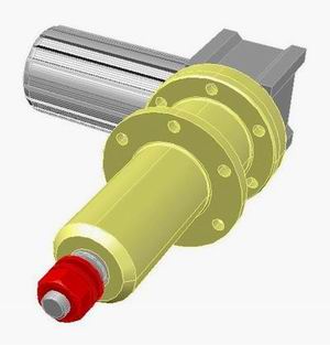
Magnetic separator
Magnetic
separator is mounted to the line frame from rear side as drawer and it
works on permanent magnet 20 cm diameter and 116 cm length and it is
driven from electric motor 2 hp and reduction gear box 1:8 which allows
all steel to be removed using one magnetic separator.
Because we use good shredding system; one magnetic separator is enough
instead of three magnetic separators in old lines where we were using
magnetic separator after shredder to protect grinder and second magnetic
separator after grinder and third before screening, since we compact all
cutting, shredding and grinding operations in one unit; then, one
magnetic separator is enough where the steel wires are com just after
its separation from the tire through trommel system without returning it
to shredding system again.
And the magnetic separator is located just before screening system and
so there is no need to additional magnetic separator before screening.
Installation of collecting table
Installation of magnetic separator
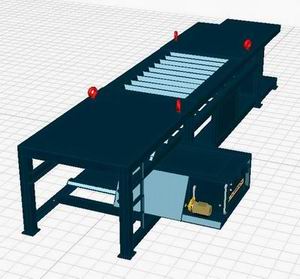
Screening system works
after magnetic separation system and fiber separation system; so we
classify the powder in this system and guarantee that the fiber is 100%
free from steel and from fiber.
Screening system installation
The screening system is
installed in production line frame as frontal drawer below magnetic
separator where rubber powder is transferred from fiber separator to
magnetic separator and then to screening system.
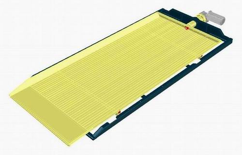
The screening system works by using screening table of 125 cm width and
4 m length, The table has four lower chambers, Over these chambers there
are four screens in different mesh sizes where the first chamber has
1/2 mm screen to separate the powder less than 1/2 mm in first chamber
and lead it to packing system.
And so the second chamber has a screen of 1 mm to separate the powder
from 1/2 to 1 mm, the third chamber has a screen of 2 mm to separate the
powder from 1 to 2 mm, The last chamber has no screens and the remaining
powder is sure from 2 to 3 mm.
Vibrating
table moves the powder on screens from smaller to bigger. This motion
helps in screening process over screens and also transfer it to the next
chambers. Vibrating motion also collects the rubber from lower chambers
and leads it to outlet of chambers. Vibrator unit is driven by electric
motor 2 hp and reduction gear box 1:3.

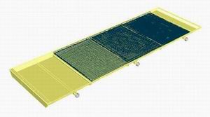
Screening system
Screens
Generally; you can change screens by any different size less than 3 mm
and also you can eliminate some sizes by mounting two desired screens
only on first and second chambers, The powder will come from first and
second screens, the rest powder will come from third chamber and the
forth chamber will get nothing.
Packing
system packs the rubber powder coming from screening system in identical
packs which are adjustable from control panel. Packing process is done
by means of four screw conveyors supported by four lower hoppers which
receives the powder from screening system and keeps it till the operator
puts an empty pack at the screw conveyor outlet and pushes the packing
button.
After the
pack is full; the operator have to bush stop button to change the pack,
the packing motor stops and the lower hopper collects coming powder till
the operator changes the pack and press the packing button again.
Packing system
In
automatic packing mode, you may press packing button and it will stop
automatically when the pack reaches to adjusted weight and it will work
automatically after a certain period of time and stops again at adjusted
weight and so on.
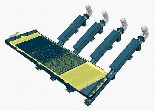
Screening and packing systems
In
automatic packing mode, you can adjust each pack on different weight and
the required weight is calibrated in corresponding time and the motors
are operated for a while where the lower hoppers are full and stops
automatically when it reaches to empty and works again to complete the
pack and so on till the pack reaches to its programmed weight and of
course the stopping periods are deduced.
And hence
we get accurate and identical weights using this packing program which
is programmed in the control system of the line.
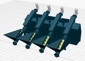
Packing augers on its base
If you
stop the screw conveyor to change the pack; the screw conveyor will work
automatically after certain time even there is no pack for fear of
blocking of powder inside the production line and you will see and hear
warning for that.
The screw
conveyors are fixed on special base to support the conveyors and
provided with outer fence to separate the packing area from production
line and it is provided also with upper platforms to fix maintenance
rails and to ease motors accessibility.
The screw
conveyors works on 30 degree to the ground which prevent powder blocking
in the screws, screw outer diameter is 20 cm and 280 cm length, It is
provided with upper cover along its length to ease auger cleaning and
remove any blocking metals.
Cooling
system works in cooling the cutting blades of shredding system which
increase blades life, In addition; cooling the blades prevent heating
rubber powder and hence better powder quality and free from smokes or
odors.
Cooling
system starts in cooling tank of 1000 lit capacity which is fixed to
production line frame from back side as a drawer. It is connected to
production line by flexible connections in separation points. The tank
has its standard ports like tank inlet, tank outlet, pump connections,
level indicator, over flow and pressure normalizing port.
Cooling system
The tank
is filled by water pump fixed on tank side and connected to the control
valves. The pump is operated by 2 hp electric motor and 3 bar pump
pressure. The pump is operated from general control panel of the
production line.
To
control cooling process; we use a set of control valves between pump and
cutting blades where the cutting blades are divided into four zones and
each zone is controlled separately.
Cooling tank installation
Control
valves can works on water pump or works directly at outer water line,
the control valves are supported by relieve valve to protect the circuit
from over pressure and to adjust the pressure in cooling circuit.
Cooling connections on production line
The
control valves are fixed on tank wall and provided with required labels
for each valve, the control valves are connected to the line through 4
cooling lines according to cooling zones, water pipes are fixed to line
frame and flexible connections are provided at separation points between
tank and frame and between upper hopper and frame.
Cooling
system is monitored by a set of pressure gauges to indicate pump
pressure, outer line pressure and cooling zones pressures. Outer line is
1 inch and cooling system is 1/2 inch.
Cooling control valves
Average
water consumption is 100 lit/hr and there is no return line or drain
line where the water is controlled exactly to cool the cutters without
any excess water.
Cooling
system is assembled during manufacturing and still assembled during
transportation.
Production line has 15 electric motors in different capacities which are
all controlled through general control panel fixed to production line
frame, The production line is programmed and controlled from touch
screen fixed on control panel and shows the line animation and
directions of rotation or any warnings.
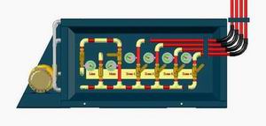
The touch screen shows also any faults in the line and how to fix it
where we prepare a complete program for the line with all its
parameters. And through this touch screen you can operate the line, stop
it, operate or stop any motor and fix the errors.
Control panel and cable tracks
In addition you can adjust feeding rate of feeding system and adjust
fiber separation sensitivity and packing sizes for packing system, where
the motors works for a certain period of time and stops till you re
operate it again.
The control panel has contactors and overload switches for each motor in
addition to general circuit breaker, programming and control devices.
That control panel is fixed to the production line frame with fixed
cable tracks which are 50 cm width and 7 cm depth and along the
production line.
Cable tracks are fixed permanently on production line and it is not
dismounted during transportation, it has upper covers for cables laying
which are removed to lay the cables and fixed again. Cable tracks have
outlets near each cable to pass the cable from it and connect the motor
later after transportation in installation site.
Control panel and tracks in fixation
In addition to using cable tracks for cables; it is used as follow up
tracks for the follow up crew to walk on.The control system of the line is fed from one electricity input cable
of 222 K.W, 380 volt, 3 phase and 50 HZ. Generally the production line
needs only one cable for electric power and one pipe for cooling water.
|
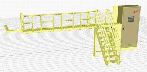
10- Maintenance and follow up tracks |
The production line is provided with a number of tracks and stairs which
are used in follow up operations and maintenance process.
Tracks starts in the side stair fixed to the production line frame and
this stair I used to follow up the feeding conveyor operation and to get
up to the production line.
Parallel to the production line; there is a follow up track with 75 cm
width and it is used to access the auger motors, to follow up the
trommel and general follow up of production line.
To follow up shredder feeding; there is side path and back ladder which
are used to follow up the vibrator of feeding system and to check the
front shredder motor.
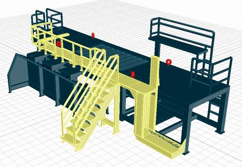
Follow up tracks
Another path is exist in the end of the line with its ladder to check
the cooling connections and air ducts beside it is used to check second
shredding motor.
This path also is used to follow up the shredding process by sight
through rear window in shredding system.
|
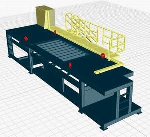
Shipping and installation of production line |
The production line is
transported in semi-assembled form where the control panel, cable
tracks, cooling system, shredding, fiber separation, magnetic separation
and screening systems are all assembled in the line frame and the
remaining parts which will be assembled in the site will be the packing
augers, fiber cyclones and belt conveyor with all their bases. Trommel
screen will also be separated into two halves and will be assembled in
site.
Assembled components during shipping
Generally, the line is
very fast in installation where four workers can install the line in one
day and we will need one shipping container 40 feet for the line and
another container 20 feet for hydraulic cutter and debeader in addition
to some external parts of the line.
The production line is
fixed to the ground by special bolts, and then the parts which were
disassembled during transportation have to be mounted in its locations.
These parts are; belt
conveyor and its base, feeding vibrator and its base, augers and its
base, cyclones and its ducts.
Stacking in shipping container
In addition; maintenance
stairs have to be fixed to its location and the main electricity cable
have to be connected to the control panel and water inlet line have to
be connected to cooling system. Then the production line is ready for
first run.
|
First run of production line |
After line installation
and connecting one electricity input to control panel and one water
input to cooling system; The line operating starts from the control
panel where a schematic diagram of the line appears on the touch screen
showing all the line systems and directions of rotations for all motors.
Any faults or
misconnections will appear also on the touch screen followed by warning
light and sound.
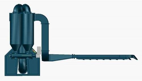
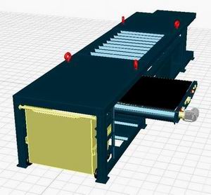
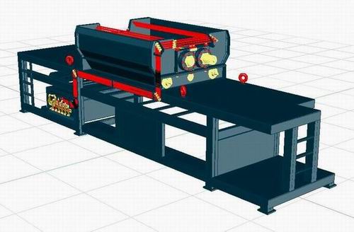
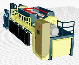
Side view of
production line
By one touch to control
panel; the line motors start running automatically and gradually to
adjust the loading of electric power to the outer line.
After the line is
operated properly; full debeaded tires have to be fed to feeding system
of the line through belt conveyor, Belt conveyor has horizontal fins on
which one tire only have to be put for each fin.Tire diameter must be
less 90 cm otherwise you have to use the hydraulic cutter to cut that
tire into halves or quarters.
Also you must use the
hydraulic debeader to remove the tire steel beads, generally these
preparations of tires have to be done in early process before line
operating.
After tires feeding are
starts, the empty packs have to be put in the packing system, Only push
the packing button and wait till the packs are full of pure rubber
powder.
When the packs reaches
to programmed weight; the packing process stops and you will hear a
sound and see a light to indicate that you have to change the pack and
push the packing button again.
In the same time, a
fiber container have to be put under the air lock in fiber separation
system and you have to push the discharge button to discharge the fiber
and wait till the container is full and then the discharge process will
stops and you will hear a sound and see a light to indicate that you
have to change empty the fiber container and push the button again.
Other steel container
have to be but at magnetic separator to collect the steel wires in it.
Wait till you hear a sound and see a light to empty the steel container
and return it again.
During containers or
packs changing; the line will continue and the powder or steel or fiber
are collected inside the line in internal temporary containers till you
change the pack and push the buttons again.
|
Analysis of production line output per hour |
|
Steel |
500 kg -- 20% |
 |
|
Fiber |
125 kg -- 5% |
|
Rubber 0 – 0.5 mm |
400 kg -- 16%
|
|
Rubber 0.5 – 1 mm |
400 kg -- 16%
|
|
Rubber 1 – 2 mm |
525
kg -- 21%
|
|
Rubber 2 – 3 mm |
525 kg -- 21%
|
|
Contaminations |
0.5 % |
|
Moisture |
0.5 % |
|
Power consumption |
222 K.W. |
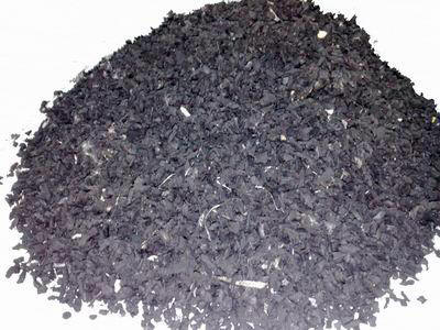 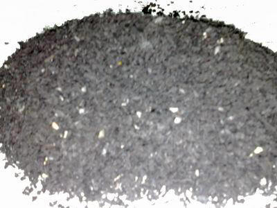 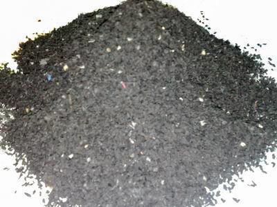 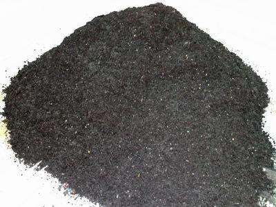
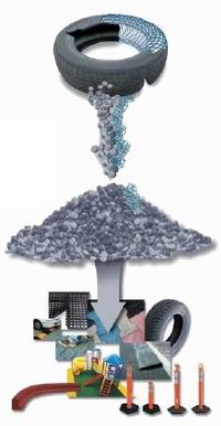
Samples of output powder
|
Some applications of rubber powder |
Rubber powder has many applications like shoes factories, tires
factories, rubber connections factories, oil seals factories, hoses
factories and likes.
Rubber powder could be also used in oil factories, vehicles factories,
brake pads factories, roads paving, stadiums flooring and some building
industries.
Sometimes the rubber powder is used as a fuel in cement factories where
one ton of tires equal 700 kg of normal fuel, Or 4 tires equal one
barrel of fuel
Click here to see another tire
recycling line 1500 kg/hr
|