|
|
Multi-purpose shredding system
Model
MS091 |
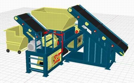
Multi-purpose shredding system
Multi-purpose shredding system is specially
designed to shred combined scrap materials including rubber,
plastics, paper, wood, tin and light metals. The shredder will
produce in one pass shredded chips of 50 mm size or smaller without
the need of any further screening. Shredding average capacity is
2500 kg/hr of input materials.
Scrap materials are fed to the shredder via 900 cm
feeding belt conveyor and the shredded chips are discharged via 900
mm discharge belt conveyor.
A low speed high torque cutting mechanism is
driven through two trouble free, heavy duty gearboxes which are
directly connected to two electric motors. The cutting mechanism
consists of two cutting axes and each axe is supplied with series of
rotating cutting blades. Rotating cutting blades pass within a
series of fixed cutting knives located at side walls of the
processing chamber. Both rotating and fixed cutters are replaceable
and re-sharpenable.
|
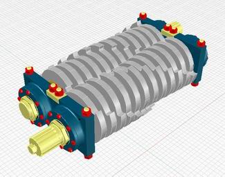
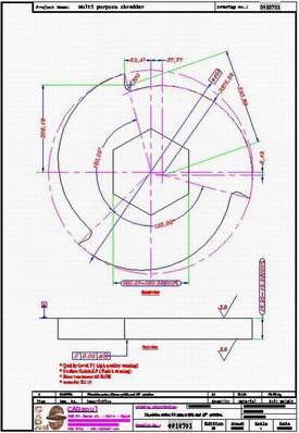
1- Shredding and grinding mechanism |
Shredding and grinding mechanism accepts the material coming from
feeding belt and shred it to chips less than 50 mm in one path.
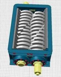
The shredding mechanism has 24 cutting blades 490 mm diameter and 50
mm thickness. The blades are assembled on two rotating axes with
1200 mm active length and 207 mm diameter.
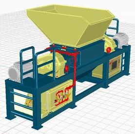
Shredding and grinding system
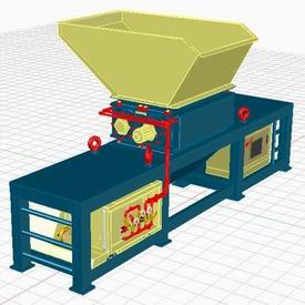
During maintenance the desired axe could be removed with all its
blades and it is easy to change or re-sharpen the blades, then
reinstall the axe without disconnecting the cooling connections
during maintenance.
Shredding chamber assembly
Each axe is driven from separate electric motor 20 K.W. and
reduction gear boxes to finally rotate the axes in 30 rpm and this
system can shred 2500 kg/hr of recycled materials in average.
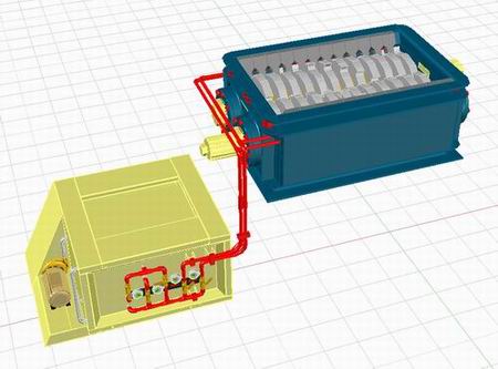
Parallel to shredding mechanism; there is cooling system which
sprays cold water on cutting blades. This system allows the blades
to be just cooled without wetting the material or needing drain
line.
Cooling system works in cooling the cutting blades of
shredding system which increase blades life. Cooling system starts
in cooling tank of 500 lit in capacity which is fixed to shredder
base from side as a drawer. It is connected to shredder by flexible
connections in separation points. The tank has its standard ports
like tank inlet, tank outlet, pump connections, level indicator,
over flow and pressure normalizing port.
The tank is filled by water pump fixed on tank side
and connected to the control valves. The pump is operated by 1 K.W.
electric motor and 3 bar pump pressure. The pump is operated from
general control panel of the shredder.
To control cooling process; we use two control valves
between pump and cutting blades where the cutting blades are divided
into two zones and each zone is controlled separately.
Control valves can work on water pump or work
directly at input water line, the control valves are supported by
relieve valve to protect the circuit from over pressure and to
adjust the pressure in cooling circuit.
Cooling system
The control valves are fixed on tank body and
provided with required labels for each valve, the control valves are
connected to the shredder frame through two cooling lines according
to cooling zones, water pipes are fixed to shredder frame and
flexible connections are provided at separation points between tank
and frame body.
Cooling system is monitored by a set of pressure
gauges to indicate pump pressure, outer line pressure and cooling
zones pressures. Outer line is 1 inch and cooling system is 1/2
inch.
Average water consumption is 400 lit/hr and there is
no return line or drain line where the water is controlled exactly
to cool the cutters without any excess water.
Cooling system is assembled during manufacturing and
still assembled during transportation.
Shredding system has 5 electric motors in different capacities which
are all controlled through general control panel fixed to shredder
frame. The control panel shows also any faults in the system by
light and sound warnings.
You can operate the system, stop it, operate or stop any motor and
fix the errors. In addition you can adjust feeding rate of feeding
system. The control panel has contactors and overload switches for
each motor in addition to general circuit breaker.
That control panel is fixed to the shredder frame with fixed cable
tracks. Cable tracks are fixed permanently on the frame and it will
not be dismounted during transportation.
The control system of the shredder is fed from one electricity input
cable of 45 K.W, 380 volt, 3 phase and 50 HZ. Generally the shredder
needs only one cable for electric power and one pipe for cooling
water.
|
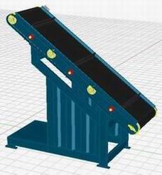
4- Feeding and discharge conveyors |
Feeding and discharge conveyors of 90 cm width and 3 m length is
mounted on robust bases and operated via electric motors 2 K.W. each
and reduction gear boxes 1/100.
Feeding belt linear speed could be controlled from 7 m/min to 14
m/min and which means 2 to 3 ton/hr of input materials where maximum
width of input materials are not more than 90cm. Conveyor belts are
provided with horizontal fins each 90 cm of belt length. These fins
of 70 mm high act as a gauge to adjust manual feeding process.
Feeding belt conveyor
Discharge belt conveyor
Feeding belt high at lower end is about 80 cm which is suitable for
manual loading and discharge belt high at end is about 190 cm which
is suitable for easy packing.
Belt inclination is 35 degree to the ground which allows high
friction force to permit the fed or discharge chips from sliding.
|
Shipping and installation of shredding system |
The
multi-purpose shredding system is transported in semi-assembled form
where the control panel, cable tracks, cooling system, shredding
chamber, lower and upper hopper are all assembled to the frame
during transportation and the remaining parts which will be
assembled in site will be the belt conveyors with their bases only.
Generally, the shredder is very fast in installation where two
workers can install it in 4 hours and we will need one shipping
container 20 feet for transportation.
The
shredder could be fixed to the ground by special bolts, and then the
belts which were disassembled during transportation have to be
mounted in their locations again.
In
addition; main electricity cable have to be connected to the control
panel and water inlet line have to be connected to cooling system.
Then the shredder is ready for first run.
|
First run of shredding system |
After
shredder installation and connecting one electricity input to
control panel and one water input to cooling system; The shredder
operating starts from the control panel where a light indicators
appear on the control panel showing all motors operation. Any faults
or misconnections will appear also on control panel by warning light
and sound.
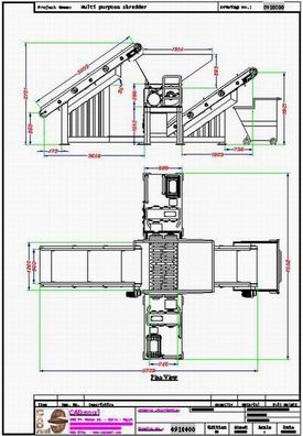
Shredding
system layout
Cutting blade dimensions
By one
touch to control panel; all motors start running automatically and
gradually to adjust the loading of electric power to the outer line.
After the shredder is operated properly; input materials have to be
fed to feeding conveyor. Input materials must be less than 90 cm.
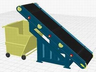
After material feeding is start, the empty packs have to be put at
the discharge conveyor for output packing.
|